![]() Prestressed concrete bridge – Per la versione in Italiano: https://www.stradeeautostrade.it/ponti-e-viadotti/patologie-dei-ponti-in-c-a-p-costruiti-a-sbalzo/
Prestressed concrete bridge – Per la versione in Italiano: https://www.stradeeautostrade.it/ponti-e-viadotti/patologie-dei-ponti-in-c-a-p-costruiti-a-sbalzo/
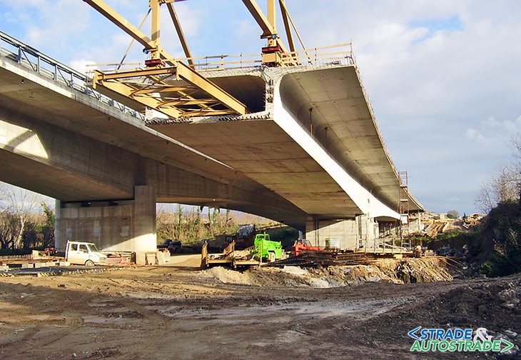
In the Seventies of the past century, in Germany, the segmental construction technique of prestressed concrete balanced cantilever girders was developed, mainly by Prof. Finsterwalder. This allowed overcoming spans greater than 100 m, previously destined for arch bridges or steel girders.
This technology rapidly spread throughout Europe and was further strengthened, primarily by the French, with the use of precast segments. In Italy, bridges with a span of more than 100 m, most of which are still open to traffic on the Italian highways and other major roads, were built with cast-in-place segments.
At the time, the isostatic scheme was used, composed of two or more balanced cantilevers at the ends of which a small dropped span was placed with Gerber hinges, generally less than 10 m long.
In the Stupino viaduct placed on the A2 highway and designed by Silvano Zorzi, the dropped span is replaced by a hinge. It was only at the end of the Eighties that the girders were made continuous by casting a key segment that merges the cantilever ends.

Most of these works have similar diseases, sometimes serious, which required important interventions or rebuilding. These criticalities are partly due to the lack of knowledge in time-dependent concrete behavior, and partly due to the prestressing system, as below better specified (see also www.mpaing.com).
The most frequent criticalities
An excessive deflection of cantilever ends has been the inconvenience that has occurred on most of these bridges. In Isostatic schemes it slightly affected the bearing capacity, but they had a considerable impact on serviceability.
The common practice was to restore the original level with pavement but, on the other hand, this increased weights and generated a vicious circle. In several concrete bridges, after the pavement removal, a deflection at mid-span of above 0.5 m has been measured!
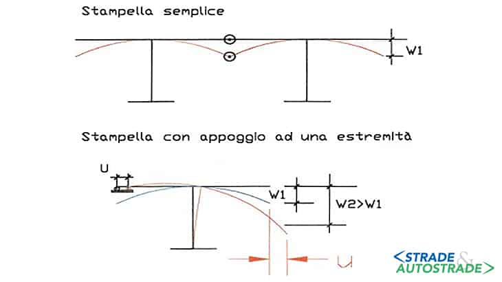
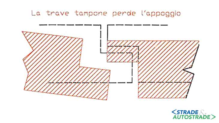
As it happens in the Ruiz viaduct of the A2 highway, the fact that one end of the cantilever cannot deflect itself because it is constrained by the abutment, gives to the other end a higher deflection associated with a horizontal displacement that can put the dropped span into crisis.
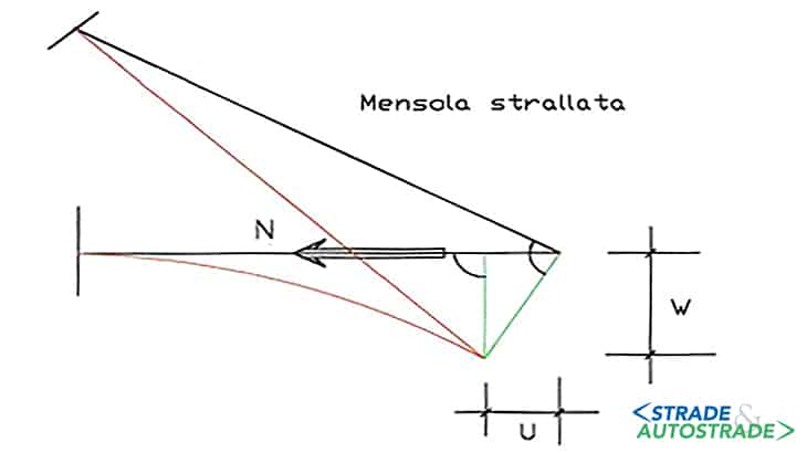
A particular case is represented by the first cable-stayed bridges ever built; they can be seen as balanced cantilevers that have the end suspended by an inclined stay that generates an axial force in the deck. In this case, the deflection is caused by the axial shortening (elastic and viscous) of the girder together with the elastic elongation of the stay, which can lead to the dropped span bearing loss.
The presence of the dropped span has triggered the typical known phenomena of degradation of Gerber hinges: seepage, mold, inability to perform inspections, etc., enhanced by the fact that many of these bridges are located in the Apennines, where the use (abuse) of de-icing salts is extremely high.
Some bridges that are prestressed by large cables can show an additional problem that is linked to the section distortion in correspondence with the cable anchorages.
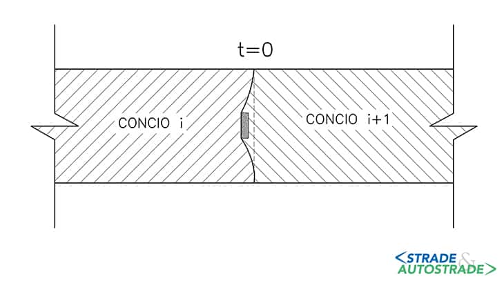
In the tensioning phase, the distortion in the “i” segment final section is hidden because the “i+1” segment is cast against the previous one, and it takes the “i” segment shape (Figure 4A).
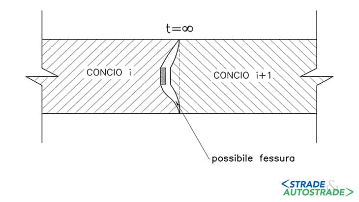
Due to the creep, the distortion due to the bar anchorage section is amplified. If there are not enough rebars or there is not enough prestressing given by the cables installed in the further phases, that could lead to a crack (Figure 4B).
The causes
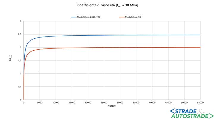
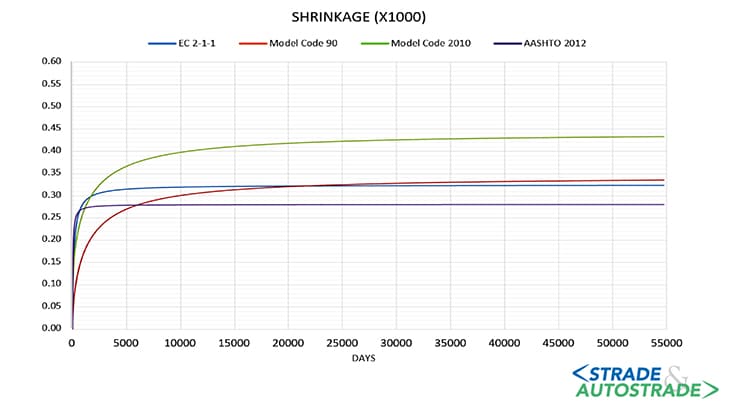
The main cause of the described excessive deformation was the lack of knowledge about concrete creep and shrinkage, which were widely underestimated at the time: for example, unitary strains caused by shrinkage are on average 50% higher than those considered in the past, while the difference is slightly lower for creep.
Creep, besides increasing the initial elastic deformation, also intensifies the prestressing losses over time, which were also underestimated in the past.
There were also greater instantaneous losses of prestressing in addition to the greater time dependent losses in these works. Indeed, these bridges were prestressed with bars produced at the time by the german Dywidag, in fact these bridges were improperly called with this name.
These bars, for obvious operational reasons, had the same length of the segment and were joined with couplers to those of the next segment.
The sheaths had diameters slightly higher than those of the bars (a 36 mm bar had a 45 mm sheath) with an enlargement in correspondence with the couplers (the coupler cover) of an adequate length: the inevitable construction errors could however lead the couplers not to slide freely in the tensioning phase, generating a sort of supplementary friction.
Tension release tests performed on Ruiz viaduct prestressing bars, revealed that the residual stress was about 300 N/mm2 instead of the 600 N/mm2 hypothesized by the Designer, who evaluated the losses with the coefficients of the time.

A similar result was achieved on Cannavino viaduct, placed in S.S. 107 “Silana Crotonese”, built in 1978. Its bars residual stress has been evaluated to be 40-45% lower than the one assumed in the original calculations.
In this case the margin of error is greater, since the tension releases have been done on the concrete, in which the unitary strains are also affected by other phenomena that do not depend on the stress state (such as the shrinkage).
In almost every case, all the examined bars were not injected, in other words non-adherent. That characteristic reduces their effectiveness at the Ultimate Limit State. However, surprisingly, they were almost completely corrosion-free.

The interventions
In the past, action was taken on some of these viaducts by adding external prestressing tendons placed inside the box girders.
Adopting this approach means restoring the required safety coefficients in the resistance checks, compensating for the lack of adherence of the original bars. Anyway, the initial geometry cannot be restored since the very aged concrete has practically no creep, therefore only the elastic deflections can be recovered.

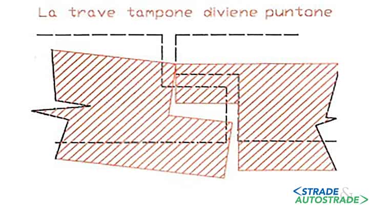
Moreover, a little help can come from replacing the dropped span with another one in lighter steel, but it is still necessary to use filler material (possibly lightened) to restore the level.
Currently, taking into account both the fact that these bridges are 40/50 years old and they have exhausted their useful life, and do not comply with the new anti-seismic codes, it is preferable to demolish them, possibly saving piles and foundations if they are suitable for carrying a lighter steel deck.
As a matter of fact, ANAS adopted for the demolition of the aforementioned Cannavino viaduct and others of the A2 highway.

This operation of destruction is particularly delicate, because decks are always integral with piers and, if the goal is not to compromise the parts to be reused, only a limited number of asymmetries in the own weights can be accepted.
Conclusions
The balanced cantilever segmental construction technique represented one of the biggest innovations in the prestressed concrete bridges field in the past century. Its potentiality has meant that across Europe, Italy included, several of this type of works were realized. The lack of knowledge of time-dependent effects and the fact that many of these bridges are more than 50 years old, frequently caused a significant degradation.

Since these bridges are always crucial, both for spans and piers height, the question is whether to repair or to replace them. The current trend seems to be a reasonable compromise: saving piers and foundations and replacing the decks with lighter ones in order to satisfy also the new anti-seismic code.
Since decks are always integral with piers, this operation is very delicate and will represent one of the future challenges.
![]() Per la versione in Italiano: https://www.stradeeautostrade.it/ponti-e-viadotti/patologie-dei-ponti-in-c-a-p-costruiti-a-sbalzo/
Per la versione in Italiano: https://www.stradeeautostrade.it/ponti-e-viadotti/patologie-dei-ponti-in-c-a-p-costruiti-a-sbalzo/