![]() Per la versione in Italiano: https://www.stradeeautostrade.it/ponti-e-viadotti/un-ponte-strallato-per-attraversare-limpervia-valle-dellanji-khad/
Per la versione in Italiano: https://www.stradeeautostrade.it/ponti-e-viadotti/un-ponte-strallato-per-attraversare-limpervia-valle-dellanji-khad/
An approximately 300 km long railway line, linking the cities of Udhampur, Srinagar and Baramulla in the J&K northern state of India, is under construction. The very difficult morphology of the area implies to bore many tunnels with a total length of about 90 km, and the construction of important bridges.
One of these crosses the Anji River about 190 m over the bottom of the impervious valley. A steel truss arch, spanning 260 m, was the initial structural solution; some piers of the approach viaduct were also erected.

Anyway, the construction was stopped immediately after the beginning because of the difficulties faced to cut the sub-vertical slopes on the left side of the valley. The extremely fractured and sheared rock was difficult to stabilize also with expensive works so that Northern Railways of India, the owner of the railway line, called for an international bid to prepare a new design and consulting for the construction works.
The tender was assigned to the Italian engineering Company Italferr of the Infrastructures Pole – Italian Railway Group with LoA dated April 2016, while the subsequent tender for Proof Checking was assigned to the Company Cowi (UK).
A new tender for construction was called on October 2016 based on the new Design developed by Italferr, then assigned to the Indian Contractor HCC. The Construction works, supervised at the beginning by Ircon Ltd and subsequently by Konkan Railway Corporation Ltd, started on February 2017 and are, at present, almost completed.

Bridge’s main features
The situation of the site concerning both orography and geological/geotechnical aspects can be summarized by the following points:
- the first layers of the rock are highly fractured (with many “shear zones”) on both sides of the valley;
- any cut in these layers can cause land slide, as the service road built in the past shows and expensive preliminary works, lasting long time, should be requested to avoid the mentioned slides;
- the deep slope on the left (Katra) side is very inclined from the bottom up to the end of the tunnel T2, while on the right (Reasi) side, there was a flat area, about 350 m long, between the slope of the river and the beginning of the already built tunnel T3.

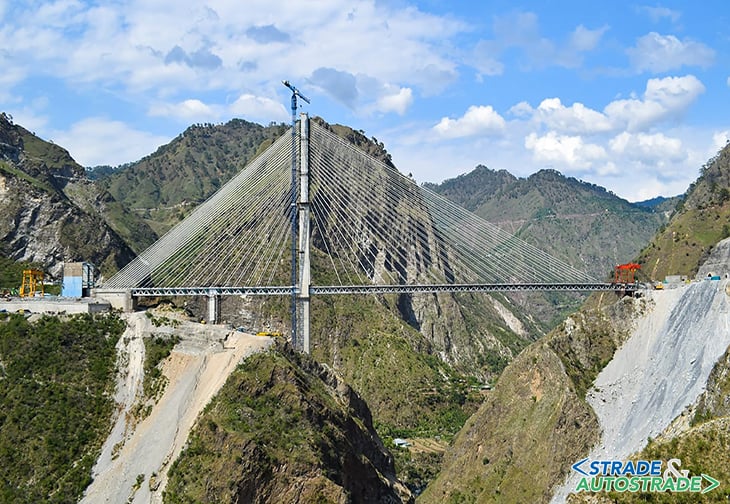
Due to the above considerations, the use of an asymmetric scheme of the bridge was imperative. Different solutions were compared before the develop of the Preliminary design and finally a cable-stayed bridge, with only one tower placed on Reasi side, in a position where the disturb to the slope is reduced, has been adopted (Figure 1 above).
The whole crossing of the Anji Valley has been subdivided in four WBS; starting from Reasì, going toward Katra, there is:
- a 130 m long approach viaduct (called “Ancillary”) on Reasi side;
- a central embankment, located between the main bridge and the approach (Ancillary) viaduct and where, due to the existing orography and geotechnical characteristics of the site all the workshops, batching plant and so on, had to be located at Reasi side, no room being available on Katra side;

- a 473 m long cable-stayed bridge, the main structure, crossing the river with a main span of 290 m (Figure 1 above);
- a connection span to the tunnel T2 made by a single supported 38 m long span between the MA1 transition pier, where the cable stayed bridge recently landed at the end of the cantilevering construction and a small abutment close to the tunnel.
Hereafter the presentation of a short description of the main structure, the Cable Stayed Bridge, both the approach viaducts and the embankment being of ordinary features.
The well foundations
In order to limit as much as possible the cutting, a well foundation has been adopted for the tower (Figure 2 above). So doing it has been possible to reach the sound strata of the rock, without disturbing the slopes, checking “de visu” the depth necessary to get this target.

With a 20 m in diameter the well excavation, temporary sustained by φ 300 mm micropiles and concrete ribs spaced @ 4 m before the final concrete pouring, has reached 20 m in deepness.
The main tower
The main tower, the so called MP1, shaped as an inverted “Y” and with a total height of almost 200 m, was completed within the year 2021. The tower can be subdivided in five sub-elements that are, the lower shaft, the pier cap, the inclined “legs” of the inverted Y, the upper transition piece where the inclined legs converge and the “antenna”, where the 24×4 = 96 stay cables are anchored.

The stay cables
Each one of the two stay planes of the bridge contain 24 stays for the Central span and 24 for the Lateral one, with a total number of 96 stays; the stay-cable system has been provided and installed by VSL.
Three stay classes are adopted with 31, 37 and 43 strands, as a maximum dimension; the stays length varies from a minimum of 83 m for the stay n. 1 near the tower up to a maximum of 295 m for the stay n. 24. All the elements of the stay cables anchorages have been dimensioned allowing the possibility of a future 5% increasing of the stay forces.
The composed steel-concrete deck
Two steel trusses of 5 m constant height, connected by cross girders that support a reinforced concrete slab, compose the deck. The steel structures have been produced by ArcelorMittal Nippon Steel India Limited in a factory located at Surat in the Gujarat region 1.800 km south of the Anji-Khad site.

The segments have been transported to site by truck and finally assembled in the site workshop for the launching (Figure 4 above).
The choice of a composite bridge section (steel and concrete) is considered convenient; the slab, made of reinforced concrete, assures a high resistance to the environmental actions (wind, rain, ice) and reduces maintenance interventions while the steel trusses guarantee light dead load compared to a high level of resistance.
The concrete slab collaborates with the steel elements, the continuity being assured by steel connectors, which are very common and tested all around the world. The global section is considered a box girder due to the presence of horizontal bracings at the level of the lower chord, also, so that a very good torsional stiffness is provided.

The 445 m long continuous truss beam is structurally connected with the MA2 abutment by means of 2×4/27 str. + 2×4/19 str. replaceable post-tensioning cables plus 2×70 φ36 passive rebars and 2×180 headless smooth φ22 stud shear connectors (Figure 5 above).
The bridge deck is 15 m wide; it is designed to carry a single railway track and a 3,75 m wide vehicles road for maintenance and emergency conditions (Figure 6).
The construction method
After erecting the 200 m main tower, the first 100 m of the rear span plus 50 m of the main one has been incrementally launched pushing the deck from the Reasì end abutment where the working shop for assembling the segments has been located (Figure 7 above).

Having installed the launching gantry on the bridge tip, the remaining 240 m length of the main span construction has been cantilevered, launching 10 m long segments and installing the stay cables until landing on the MA1 Katra transition pier.
Each new segment to be launched has been placed and moved sideways all along the deck and through the gantry; than the segment has been lifted by the gantry, cantilevered, rotated and lowered in the final position for the fastening to the portion of deck previously launched (Figure 8 above).
During this cantilevered construction phases the stays have been progressively installed and simultaneously tensioned operating symmetrically with respect to the tower; taking into consideration that two planes of stays are present, for each newly launched segment four stays had to be installed and simultaneously tensioned.

At the moment, having completed the cantilever construction of the main span, just the final tuning of stay cables and the concreting of the last macrosegment is the balance for competition of the bridge (Figure 9 above).
Conclusions
In some cases, as for the crossing of the impervious Anji-Khad valley, the structural design of a bridge, its construction method as well as its architectural shape, is mainly shaped by the environmental condition of the site: the correct interpretation of the signals given by the nature, utilizing up to date materials and technologies, is the task of the Designer.

Technical data
- Client: Northern Railway of India
- Employer: Konkan Railway Corp. LT
- Consultant: Italferr SpA – Gruppo FS Italiane
- Eng. Support services for concept, preliminary and detailed design: Mario Petrangeli & Ass. Srl
- Design Coordinator: Prof. Mario Paolo Petrangeli
- Project Manager: Eng. Roberto Di Bianco, Eng. Stefania Albanesi, Eng. Surjit Singh of Italferr SpA
- Project Engineer: Eng. Andrea Polastri of Mario Petrangeli & Ass. Srl
- Proof checker: Cowi
- Contractor: HCC – Hindustan Construction Co. Ltd
- Sub-Contractor for steel structures: ArcelorMittal Nippon Steel India Limited
- Sub-Contractor for stay cables: VSL India Private Limited
- Sub-Contractor for bearings and seismic devices: Mageba India
- Start of works: February 2018
- Estimated competition of structural works: September 2023
![]() Per la versione in Italiano: https://www.stradeeautostrade.it/ponti-e-viadotti/un-ponte-strallato-per-attraversare-limpervia-valle-dellanji-khad/
Per la versione in Italiano: https://www.stradeeautostrade.it/ponti-e-viadotti/un-ponte-strallato-per-attraversare-limpervia-valle-dellanji-khad/
> Se questo articolo ti è piaciuto, iscriviti alla Newsletter mensile al link http://eepurl.com/dpKhwL <