![]() Per la versione in Italiano: https://www.stradeeautostrade.it/materiali-e-inerti/soluzioni-sostenibili-per-i-rilevati-stradali-dello-storstrom-bridge/
Per la versione in Italiano: https://www.stradeeautostrade.it/materiali-e-inerti/soluzioni-sostenibili-per-i-rilevati-stradali-dello-storstrom-bridge/
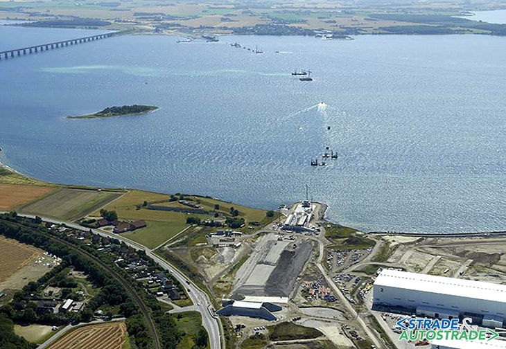
The new Storstrøm bridge is a road, railway, bicycle and pedestrian bridge that will connect the islands of Falster (region Falster) and Masnedø (region Sjælland) in Denmark, and it is currently being built by SBJV, a joint venture of Italian Contractors lead by Itinera SpA (see “Strade & Autostrade” n. 151 January/February 2022, page 152).
With a length of approximatively 4 km above water, the new Storstrøm bridge will be the 3rd longest bridge in Denmark after the Storebælt and the Øresund bridge. It will further strengthen the road and high speed railway connection along the route Copenhagen-Germany, when the Fehmarn Belt underwater tunnel will be completed. Client of this bridge is the Danish Road Directorate (Vejdirektoratet) of the Danish Ministry of Transport (www.andermanngroup.com).
The two central spans of the bridge are cable-stayed (overall length of 320 m), while the other 44 spans (length of 80 m each) consist of prefabricated box girder elements, as well as most of the piers (composed by different elements) and pier foundations.
, while the other 44 spans (length of 80 m each) consist of prefabricated box girder elements, as well as most of the piers (composed by different elements) and pier foundations")
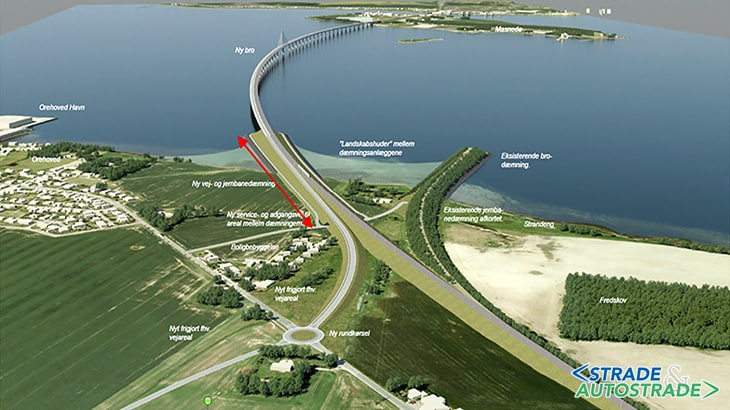
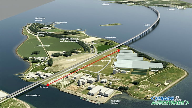
Given the complexity and unicity of this infrastructure, not less critical is the design of the connections with the secondary roads at the North and South side of the bridge. In this respect, following the proposal of the Client, SBJV has taken the opportunity to substitute part of the material in the main embankments with slag, i.e. a residual product of the incineration of domestic and industrial waste.
Figures 2A and 2B illustrate where it is planned to use this material (red arrows), for an overall volume of 100’000 m3 in the South embankment (Falster) and 150’000 m3 in the North embankment (Masnedø).
The slag used for the embankments is a recycled material with negative EPD-value (Environmental Production Declaration) due to the significant absorption of CO2 during the maturation process following the incineration. Therefore, the overall cycle produces heating, electricity and a construction material (the slag – Figure 3).
This choice is based on a principle of sustainability and it comes necessarily with specific measures to avoid any environmental impact.
The necessary measures to use the slag are described in more detail in the following paragraphs, and consist of:
- definition of the limiting values for the use of slag;
- definition of criteria for the stockpiling of the slag;
- geometric sealing o the volume of slag;
- collection in a closed drainage system of any water that leaches through the slag.
Limit criteria for the use of the slag
In order not to be classified as a dangerous waste, the slag must contain a quantity of metals within the limits defined in Figure 4.
The same criteria are valid on the South side (Guldsborgsund municipality) and on the North side (Vordingborg municipality) of the bridge.
Criteria for the stockpiling of the slag
In both the municipalities involved by the use of slag, SBJV will notify to the local environmental authority, within four weeks from the decision to use slag, all the necessary information about where the receiving stations and temporary stockpiles for slags will be placed, where the slags will be used (X, Y, Z) and the date for start and finish of the use of slags, for a preliminary approval.
Slags in temporary stockpiles shall be separated from the naked earth below by means of a minimum 10cm thick layer of sand or gravel. Unauthorized people shall be prevented from entering the areas, for example by marking or fencing. Precautions (e.g. earth ditches) shall be taken to prevent surface water from the temporary stockpiles overflowing surrounding areas.
The slag shall not give significant dust nuisances, and shall be kept moist or covered, if there is a risk of dust nuisance. It is the local environmental authority who evaluates whether dust nuisance is significant.

Geometric sealing of the volume of slag
The slag shall not be used below level +3 m from the Project reference level (DVR90). Such level represents on average the existing terrain, therefore the slag is used sufficiently above the groundwater table and above the sea level, which are both around elevation 0+DVR90, to avoid any contamination.
At the base of the slag volume in the main embankments, under a layer of coarse sand (0÷4 mm), an impermeable bentonitic membrane shall be placed to convey the leaching water into closed drainage systems that are designed at regular intervals, see next paragraph. It is accepted that the membrane is not continuous in the North embankment, while it is continuous in the South embankment with slopes to facilitate the drainage (Figure 5).
The cover layer of the slag shall be constituted by clay with a maximum permeability of 10-8 m/s and shall be compacted to at least 95% of the Proctor value. At least five measurements of permeability shall be done in a trial field with extension of 1’000 m2, with a tolerance in the construction of the clay layer of +/−3 cm.
The paved surfaces above the slag volume shall have an asphalt thickness of at least 150 mm, while the pedestrian/bicycle path and the verge between roadways shall have an asphalt thickness of at least 70 mm.
It is allowed to design the subgrade drainage inside the slag volume, but only if it is placed just below the interface between road layers and slag, and in any case surrounded by draining material (gravel).

Realization of a closed drainage system
The Client (Vejdirektoratet) has expressed in an “Employer’s Change Note” the criteria and the materials to be used for the drainage of any possible volume of water that, after leaching through the slag, cannot be disposed through the main drainage system of the infrastructure (discharging in an infiltration basin and eventually in the sea), but shall be collected and monitored inside a closed system.
It should be noted that, for the operational phase, the risk analysis carried out by the Client with its consultant (COWI) didn’t envisage a significant probability of penetration of water in the slag due to its geometrical sealing and to the presence of a drainage system for all the surfaces.
However, since this project involves the largest amount of slag ever used in in Denmark, the opportunity is taken to implement a system of collection and monitoring (independent from the prescriptions of the municipalities) to verify if the assumptions of isolation of the slag during operational phase were correct. Only during construction some leaching is expected due to the use of extensive amounts of water on the slag for the purpose of compaction.
")
With reference to Figure 6, the closed drainage system consists of the following elements:
- perforated Ø110 mm pipe surrounded by a gravel filter that receives the water collected by the bentonitic membrane;
- a corrugated Ø425 mm raising pipe (gully) for the collection of the liquid from the perforated pipe, that should have its base at +3 m DVR90 and emerge by at least 0,5 m from the embankment outer surface;
- a closed Ø110 mm sloping uPVC pipe, to discharge in the inspection gully;
- a Ø1.000 mm concrete inspection gully, which is the destination of the possibly contaminated liquid with a 900 mm high sand trap. This gully is at the foot of the embankment and its top shall emerge by at least 1 m from ground level. Below the corrugated pipe, two layers of bentonite membrane must be applied and shaped in a way to reach the clay layer.
The grain size distribution of the coarse sand (0÷4 mm) covering the bentonitic membrane, as well as the gravel covering the perforated pipe, are established by the Client in order to provide sufficient permeability.
The bentonitic membrane and the drainage system have also the purpose of monitoring the amount of leaching water, not yet known. Is any liquid will be found in the inspection gullies, such liquid should be sampled and examined by the environmental authority and re-used only to hydrate the same slag volume. Inspection gullies shall never overflow, and the liquid shall be disposed only by authorized personnel (in any case, it will not be a duty of SBJV).

Technical data
- Client (Contracting Authority) and Project Management: Vejdirektoratet (Danish Road Directorate)
- General Contractor, Construction Management and Work
- Execution: SBJV (Storstrøm Bridge Joint Venture)
- Preliminary abd Detailed Design: SBJV (Project Managers: Andermann Engineering and Studio Geotecnico Italiano)
![]() Per la versione in Italiano: https://www.stradeeautostrade.it/materiali-e-inerti/soluzioni-sostenibili-per-i-rilevati-stradali-dello-storstrom-bridge/
Per la versione in Italiano: https://www.stradeeautostrade.it/materiali-e-inerti/soluzioni-sostenibili-per-i-rilevati-stradali-dello-storstrom-bridge/