![]() Per la versione in Italiano: https://www.stradeeautostrade.it/tecnologie-e-sistemi/flussi-di-lavoro-bim-nellingegneria-dei-ponti/
Per la versione in Italiano: https://www.stradeeautostrade.it/tecnologie-e-sistemi/flussi-di-lavoro-bim-nellingegneria-dei-ponti/
BIM development
Since the beginning of the time of Building Information Modelling (BIM) the aim over these years of strong development effort was offering a continuous workflow for designers. In particular, about structural engineering, that workflow includes the structures modelling, dimensioning, structural analysis and of course drafting and R/C detailing in one BIM environment.
Talking about the complex bridge engineering environment, the BIM development started some years later, taking into account the diversity and complexity of such kind of structures.
Depending of the project demands a switch between the new BIM approach and the classical working workflow is anyway possible and sometimes recommendable.

Closed vs open BIM for structural engineering?
The common definition of a local (Closed) BIM system is if all project co-operation partners are working on one BIM software platform. The advantage in this kind of co-operation between architects, MEP engineering, Structural Engineers and the construction Company is the effectiveness of time and the sharing of data in the same data base and on the same platform. Any information and any process is available at a glance, especially for the Client.
In the reality the Structural Engineers are faced with a lot of different data formats from different projects partners. A so-called Closed (local) BIM workflow based on one software platform is an ideal solution but in practice unfortunately not always adaptable.
To solve this reality data exchange problem the expression Open BIM is gaining over the years more and more importance.
An Open BIM solution allows the data exchange between different software data bases. One of the bases of an open BIM Workflow is the IFC format (Industry Foundation Classes), that exists for some decades now.

With the help of the building smart association where all important international engineering offices and software manufactures are members, this IFC format and the new the SAF (Structural Analysis Format) is getting now more and more of importance.
This again leads now a seamless integration of an BIM work-flow without a common data base on a same software. That is important for an effective work for BIM based structural engineering.
Software development
Software is not providing any BIM technology, designers need to implement a proper workflow, of course supported by software.
Case study has been developed with SOFiSTiK and Autodesk ® Revit® software. Over the years the SOFiSTiK FEA software solutions were always open to different kind of workflows.
This same open-minded approach is now also implemented in the BIM-Workflow, in Bridge Engineering, as well in Building Design. One first step for the Open BIM approach was done years ago with an interface and app for the software RHINOCEROS by McNeal.

Over the years the RHINO programming environment called GRASSHOPPER is one of the main effective tools for the connection of SOFiSTiK FE Models with the TEKLA BIM solution or others.
The next step is now the direct implementation of an IFC connector that allows the import/ export of data bases from other software solutions outside the Autodesk® environment.
With the additional implementation of the SAF format in the SOFiSTiK environment a new option now for an Open-BIM solution is possible. One advantage of the SAF format data exchange is that it’s base is on Excel and for this suitable for any kind of exchange without any loss of data base information.
On the other hand, with the integration of the BIM workflow for Building Design and Infrastructure Engineering in Revit®, the SOFiSTiK apps offers also a local BIM workflow in one software environment. Revit® development tools like Dynamo® allows in this case additional further developing of routines in the closed BIM.

Continuously developed and customer driven improved since years on any release of Autodesk® Revit® the SOFiSTiK Bridge and Infrastructural Modeler app is the essential BIM solution solving parametrized infrastructural projects like bridges, tunnels, noise protection walls, retaining walls or other structures.
Based on an axis definition, the infrastructure projects can be parametrically defined as native Revit® object and used for further BIM processing in the full local BIM workflow. This workflow allows now the use of Revit® in conceptual, preliminary and detailed design of the structures and a connection with the SOFiSTiK FE analysis.
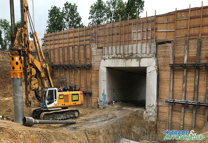
A BIM case study: motorway bridges on the bab 3 between nuremberg and regensburg in Germany
The here explicit chosen examples for the case study are simple, but not peril free, showing the daily work of Structural Engineers using the new BIM technology on a demanding geometry with huge time pressure. Designer is HFR Ingenieure from Munich which is a young and innovative team of structural professionals with high knowledge in engineering and advance experience in all kind of structures.

As a design package of three small motorway bridges on the BAB 3 between Nuremberg and Regensburg in Germany, HFR Ingenieure performed following structures:
- BW446a, replacement of the existing public underpass over a country lane as open frame structure – length 9.305 m, width 31.60 m and height 4.74 m;
- BW447a, replacement of the existing public underpass over a country lane as open frame structure – length 8.70 m, width 32.60 m and height 4.832 m;
- BW448a, replacement of the existing public underpass over a country lane as open frame structure – length 11.06 m, width 33.158 m and height 4.774 m.
The Client is Die Autobahn GmbH des Bundes, Niederlassung Nordbayern, Nuremberg and the construction Company is Strabag AG. During the initial project meetings Strabag demanded the need of a 3D BIM design of the three structures in Revit®.

The reason for this demand is to use the Revit® BIM model in further 4D and 5D workflows. In a 4D BIM workflow the Revit® model is used to the implementation in the construction time scheduling process. In the 5D BIM workflow the Revit® model is used for the accurate cost estimation and forecast of the building costs.
The structure of this overpass is like Figures 2, 3 and 4 are showing, including a variable axis and two Construction Stages. To fullfill the demands of the construction Company HFR Ingenieure implemented a new BIM workflow in their design process.
The first step is the generation of the structure in Revit® with the use of SBIM and additional programming routines in Dynamo®. As next step the structure is analyzed in the SOFiSTiK FE software. Afterwards the construction and formwork drawings are being created directly out of Revit® with SBIM.

For the reinforcement drawings generation HFR decided to use a hybrid solution. Some smaller complex details are drawn in 3D reinforcement in Revit® with the help of the SOFiSTiK Reinforcement app, but the main drawings are done with SOFiCAD in the standard AutoCAD environment. Exporting the drawings directly from SBIM to SOFiCAD was a very effective and time saving solution in the process.
The figures 5 and 6 are showing the bim workflow for this bridge.
As the design team were faced to some problems with some self-joining elements in the stage of modelling, they decided to program some routines in Dynamo® to solve this issue. The abutment is joint by eight wall elements. Due to the complex clothoid geometry a control of the joining order was not possible. The solution was to create an on shape element that solves this problem.
The construction drawings generated with SBIM were directly exported as PDF drawings. Mostly in 2D, but in some cases as Figure 7 shows as 3D to with the alignment points of the abutment.

Conclusion
After the first-time consuming design of the first of the bridges, the other two ones were designed faster and more effectively than in the normal so far used standard workflow. Changes applied from to the construction process and adaptation of the FE Model and drawings were done very fast.
The use of BIM technology for designers like HFR Ingenieure is definite an improvement. The central model for further processing, like construction process scheduling, costs calculation, lifecycle management or monitoring of a bridge is a huge step towards a future effective and efficient bridge design technology.
To find out more, contact the authors at the link Contatti – venmises %.
![]() Per la versione in Italiano: https://www.stradeeautostrade.it/tecnologie-e-sistemi/flussi-di-lavoro-bim-nellingegneria-dei-ponti/
Per la versione in Italiano: https://www.stradeeautostrade.it/tecnologie-e-sistemi/flussi-di-lavoro-bim-nellingegneria-dei-ponti/