Safety devices built by ANAS ![]() Per la versione in Italiano: https://www.stradeeautostrade.it/its-smart-road/i-dispositivi-di-sicurezza-anas/
Per la versione in Italiano: https://www.stradeeautostrade.it/its-smart-road/i-dispositivi-di-sicurezza-anas/
The Safety Barriers Sector of the Territorial Operations and Coordination Department of ANAS SpA coordinated by the author, following the specific requirements related to planned maintenance work, has developed new high-performance median barriers.
H4 ST DSM barrier (steel median barrier H4B class with motorcycle protection system, called DSM)
In February 2019, we tested a new steel median barrier called H4 ST DSM. The tests conducted to get CE marking for the system gave back very positive results. The crash test with the light vehicle confirmed the design expectations since the ASI index (Acceleration Severity Index) representing accelerations to which the vehicle occupants were subjected was 1.37.
The heavy vehicle test provided an indicator of absolute importance in connection with the working width “W” of the barrier, whose value achieved is unique in Italy with containment class and barrier characteristics being equal. Being able to have a barrier only 76 cm wide with a W4 value of 1.28 m will allow ANAS to resolve critical situations marked by limited installation conditions.
These high-performance results were obtained by inserting a second steel rod coupling at the height of 84 cm from the base of the barrier as compared to the first one at the top of the bar, at about 153 cm.
The ANAS DSM (motorcycle protection system)
The entire range of ANAS steel barriers fully meets the latest requirements introduced by Italian Ministerial Decree of April 1st 2019 “Road safety devices for motorcyclists (DSM)”. The main objective of ANAS barriers is to prevent serious injury to motorcyclists with use of the motorcyclist protection system (DSM), which prevents direct contact against the posts and the sharp edges of the wave profile during impact.
Generally speaking, introduction of the DSM structurally integrated with the restraint system makes the behaviour of the ANAS barriers comparable to that of continuous barriers, unlike the existing barriers fitted with exposed posts (discontinuous barriers).
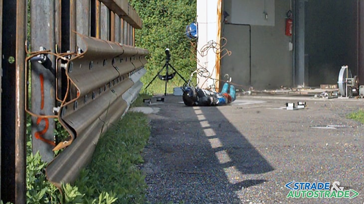
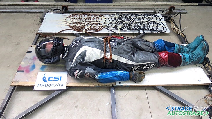
To check proper operation of the DSM, tests according to the European technical specification CEN/TS 1317-8 were conducted with the launching of a dummy against the barrier. The dummy was fitted with sensors positioned matching the vital parts of the human body (head, first vertebra and chest).

The NDBA (National Dynamic Barrier ANAS)
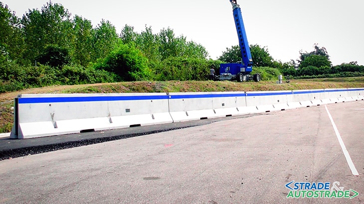
The latest project developed by ANAS SpA concerned the NDBA (National Dynamic Barrier ANAS) barrier as a traffic divider in the two configurations on the ground and on the kerb.
This innovative restraint device was developed with the aim of solving numerous critical issues encountered during scheduled maintenance work on existing roads, mainly caused by problems with installing safety barriers in limited median barrier installation conditions.
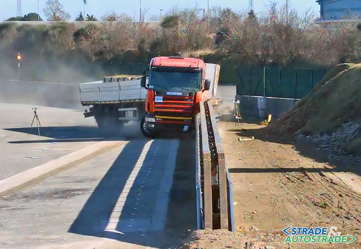
For the purposes of certification of the new NDBA barrier in compliance with the UNI EN 1317 European standard, crash tests TB 11 and TB 81 were carried out. The tests involve a vehicle weighing 900 kg launched at a speed equal to 100 km/h and an impact angle of 20°, and a 38 t articulated lorry launched at a speed of 65 km/h and an impact angle again of 20°.
The TB 11 test made it possible to detect a B level of severity of the ASI index. The results of the TB 81 test confirmed the data collected in the dynamic simulation phase, i.e. with an operating width W2, thus recording an important result if compared to devices generally available on the market.
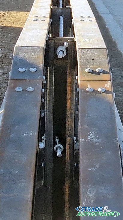
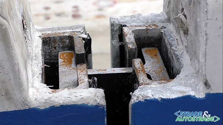
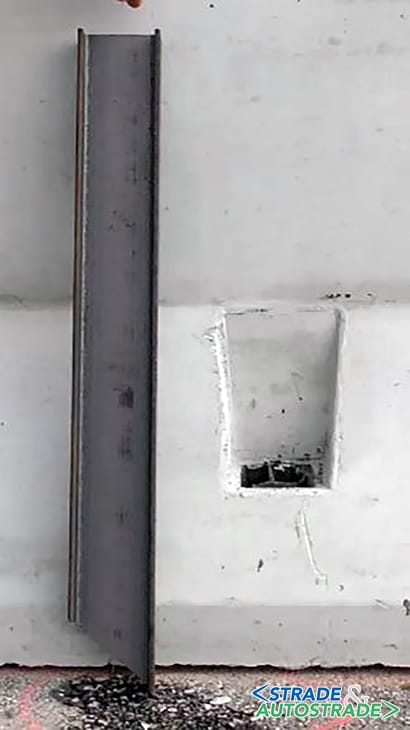
The main innovative feature that made it possible to achieve these important results for the new NDBA barrier is related to the definition of a new connection system between the modules made using a HEM 100 section bar (33 cm long) which rigidly connects the adjacent modular elements (inside of which two C-shaped steel section bars are inserted during the production phase).
The kinematic mechanism that is generated during the impact produces a more limited instantaneous and permanent deformation than that which would occur with the traditional hinge constraint.
The road restraint device has also reached high performance levels with particular reference to the ASI index (equal to 1.26) whose reduction was possible using a new barrier geometry that, through three different planes having different inclinations, contributes to damping the kinetic energy following the impact.
The individual modular concrete elements are placed directly on the wear layer of the road metal, without requiring any foundation structure. This offers clear advantages in terms of ease of installation and low routine maintenance costs.
The new barrier is also “dynamic” in that, through the different constraint configurations available, it can be adapted to the various design cases according to the space available, the type of road, the levels and the type of traffic. That means that it is the barrier that finally adapts to the road and not the other way around, as has been the case up until today.
The new barrier also features important elements of technological innovation since a system built into the device as that can alert the ANAS Control Rooms in real time of any damage to the device following an accident has been designed.
With this system, immediate rescue for users involved in a road accident, prompt intervention to restore traffic as well as signalling the potential danger to other arriving users will be made possible.
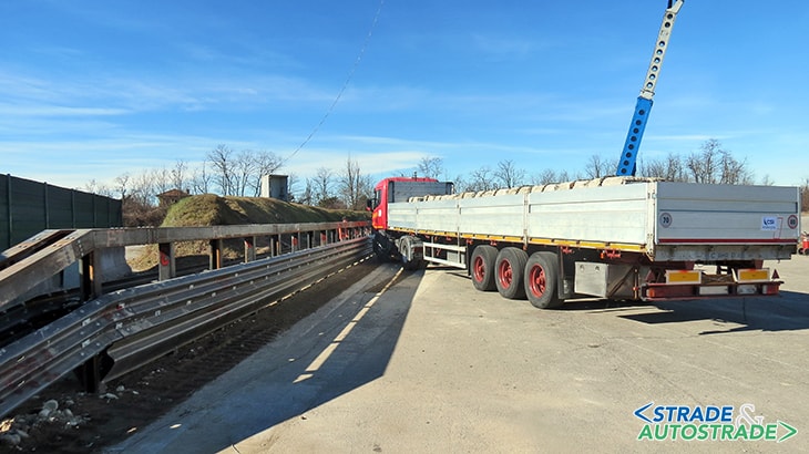
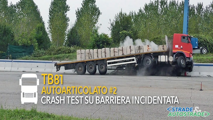
Finally, with respect to the tests strictly necessary for certification of the barrier provided by the mandatory legislation, ANAS SpA wanted to take a step forward in order to verify the response of the barrier in the case of multiple or immediately subsequent accidents.
In fact, another 38 t heavy vehicle was launched on the already damaged barrier (Second Test TB 81); the results obtained were surprising in that the barrier successfully resisted also the second collision, recording crash test parameters practically identical to those obtained during the first test.

The NDBA median barrier on kerb
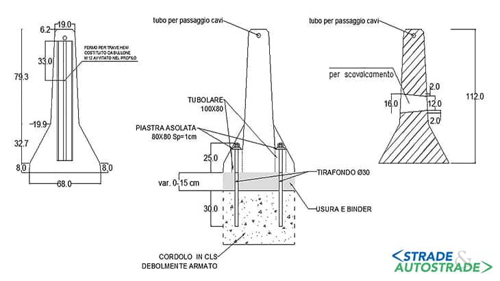
In addition to the ground configuration, a version of the NDBA barrier on kerb was also subjected to crash tests for CE marking purposes. The geometric characteristics of this latter safety barrier and the requirements leading to its certification are similar to those of the ground NDBA previously described.
Also, in this case the concrete modules are connected to each other by a HEM 100 section bar joining the adjacent modular concrete elements (inside of which two C-shaped steel section bars are embedded during the production phase).
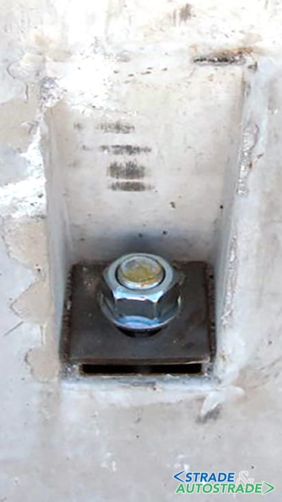
Compared to the NDBA barrier on the ground, the concrete modules in the NDBA configuration on kerb are anchored to the foundation with six M30 bolts arranged with three pairs of bolts on each side at a constant centre distance.
The tests conducted for this latter barrier as well confirmed the assumptions made during the design stage: the an ASI index (Acceleration Severity Index) equal to 1.38 (Impact Severity Level B) and Working Width equal to 0.77 m (W2 class).
The ASI comparison for the two ANAS median barriers in steel and concrete
We have been used to examining graphs like those shown below, in which the ASI index diagrams are compared based on time for steel and concrete barriers.
In the case of a steel barrier, the contact time is longer and the peak of the ASi index is lower than that recorded in the case of impact against a concrete barrier, in which the ASI reaches the peak value almost instantly and the contact time is much shorter.
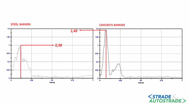
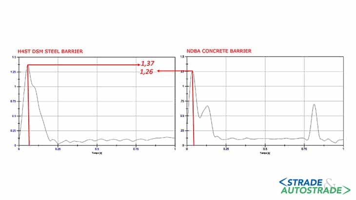
The results obtained by the two ANAS single-row median barriers invert the trend of the experimental data (Figure 10). The ASI index of the concrete barrier is lower than that recorded for the steel barrier, and the contact time is comparable in absolute terms.
These results are attributable to a new geometry of the NDBA barrier that, thanks to the adoption of three different surfaces, significant dampen the kinetic energy following impact.
Safety devices built by ANAS ![]() Per la versione in Italiano: https://www.stradeeautostrade.it/its-smart-road/i-dispositivi-di-sicurezza-anas/
Per la versione in Italiano: https://www.stradeeautostrade.it/its-smart-road/i-dispositivi-di-sicurezza-anas/