![]() Per la versione in Italiano: https://www.stradeeautostrade.it/gallerie-e-tunnelling/saint-denis-un-tunnel-scavato-sotto-falda/
Per la versione in Italiano: https://www.stradeeautostrade.it/gallerie-e-tunnelling/saint-denis-un-tunnel-scavato-sotto-falda/
The project
The municipality of Villeneuve-la-Garenne, belonging to the banlieue of Paris, promoted a project for the burial of 15 km of high voltage cables (MESIL – Mise En Souterrain d’Initiative Locale).
This project will allow the demolition of 27 overhead masts within the municipal ground, gaining 80 hectares of free surface for future development.
")
For this purpose, RTE (French multiservice Company for electricity distribution) has decided to construct a 2,4 km long tunnel, excavated with TBM technology, with 4 m diameter and at a depth of 50 m below ground level, running alongside the Seine river in Saint-Denis (www.enser.fr).
The works were executed by Spie Batignolles Génie Civil, one of the main French Contractors.

The works
The project consists of the following main works:
- the entrance shaft (Seine shaft);
- the exit shaft (Briche shaft);
- the tunnel.

The entrance shaft (Seine shaft)
The entrance shaft for the TBM has an elliptical contour (internal dimensions: major axis 16,5 m; minor axis 13,5 m) and a depth of 49,4 m. In operational conditions the cables from the electric power plant will go down into this shaft and enter the tunnel.
The shaft will host the technical rooms for ventilation and smoke extraction system in case of fire inside the tunnel.

The perimeter of the shaft is built with concrete diaphragm walls 104 cm thick and 62 m deep, reaching the layer of Calcaire Grossier. Injection have been carried out for the waterproofing of the base of the shaft.
The thickness of the concrete raft foundation is 1,8 m, anchored to the diaphragms and designed to resist, in long term conditions, to an upthrust resulting from a 46,8 m water head.

The shaft cover consists of a 50 cm thick concrete slab, with top level 1 m below ground. This structure has three holes:
- the hole for the ventilation of the shaft;
- the hole to lower bulky loads down the shaft;
- the hole for the access stairs.
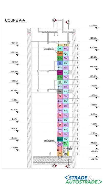
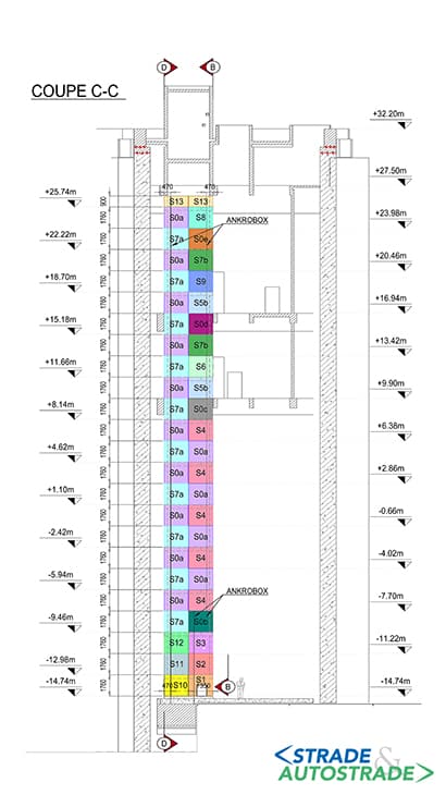
The access stairwell (with REI 120 fire resistance level) is made up of C-shaped precast modules. Its internal dimensions are 3×5,88 m and they have been defined to allow the passage of a stretcher in case of emergency. Each of the 26 flight of stairs has a rise of 176 cm, and intermediate floors are cast in place. The stairwell structure is eccentric with respect to the geometrical centre of the ellipse.

The Seine shaft has three intermediate levels: S1, S2 and S3. Each of these levels is supported by two main cast-in-place beams (parallel to the minor axis of the ellipse and anchored to the diaphragm walls) and three or four precast secondary beams perpendicular to the main ones.
The stairwell structure is meant to be structurally disconnected from the intermediate levels, in order to avoid the transmission of parasite forces. The stairwell structure should transfer its weight only to the 1,8 m thick concrete raft.
The walls of intermediate are built with hollow core wall panel laid on the beams and filled with concrete poured on site. Walls at level S3, S2 and S1 are 6 m, 8,2 m and 3,2 m high respectively.

Beams at levels S3 and S2 are meant to sustain only the structures of their level, while beams at level S1 bear this level and the loads of the cover slab, which is supported by the internal walls.
The exit shaft (Briche shaft)
The exit shaft of the TBM has a circular shape (internal diameter: 15,2 m) and is less deep than the entrance shaft (17,5 m depth). From this shaft the high voltage cables will rise to get into two surface tunnels and connect again to the overhead mast system.

Also the perimeter of this shaft is built with concrete diaphragm walls, 62 cm thick and 26 m deep, and has a stairwell shaft with the same geometry of the one in Seine shaft. The shaft cover consists of a 1 m thick concrete slab, with top level 1 m below ground, and connected to the walls through couplers.
The tunnel
The tunnel with circular section (internal diameter 3,1 m) has a length of 2,4 km and is excavated by a TBM (external diameter 3,9 m) named Ambre and provided by Herrenkneckt.

The axis of the tunnel is at ─13,40 m NGF (Nivellement Général de la France) at the entrance and at +21,50 m NGF at the exit, for a positive elevation gain of 34,9 m and an average slope of 1,4%. The final tunnel lining consists of precast concrete elements.
Construction phases
The excavation of the shafts
The excavation of the two shafts was performed by the Contractor Capocci. Due to the vicinity of the Seine river it was possible to dispose excavated material using barges, with a lower environmental impact respect to more traditional methods (trucks).

The excavation of the tunnel
The TBM excavation has been carried out with a constant monitoring of settlements, since the path of the tunnel crosses major infrastructures, among which:
- Highway A86;
- the Saint-Denis channel;
- a railway embankment with four tracks.
The TBM Ambre was launched in May 2021.
The excavation was performed permanently under groundwater level, with a pressure of approx. 4 atm at the head of the TBM. In July 2021 a specialized team was required to replace some shield elements through a hyperbaric intervention.

The team had to undergo cycles of preparation in the man lock, and all operations were performed within a limited time frame (45 mins). At the end of the TBM excavation the Briche shaft was flooded to compensate the hydrostatic thrust. The TBM operations were completed in May 2022.
Internal structures of the tunnel
Once the tunnel excavation was completed, internal structures construction has begun. The precast modules of the stairwell column (approx. 10 t each) were installed and connected through rebars grouted inside corrugated steel sleeves.

To speed up the installation of the floors between stairways modules, a standby box system (Stabox) has been provided on modules’ walls. The casting of intermediate levels was also very quick, thanks to the large number of precast elements (reinforcement cages, beams, floor slabs and walls).
Design challenges
The calculation models
The numerical models for the design have been developed through the software SOFiSTiK. Technical challenges in this context are mainly related to the correct modeling of the connections between structural elements, and of interface with the diaphragm walls, in particular for the concrete rafts and cover slabs of the two shafts.

BIM
Geometrical models of Seine and Briche shafts have been made with AutoCAD Revit in order to export the geometry in .ifc format.
This procedure allowed the definition of several functional details of various mechanical and electrical systems to be installed, as well as the management of precast modules, in particular for the stairwell.
Conclusions
The design of this project required multidisciplinary competence. Enser skills was an added value for the Contractor Spie Batignolles Génie Civil during the entire execution phases, ensuring a high quality level in the implementation of complex numerical calculation and in the drafting of technical drawings created in a BIM environment.
The design services were oriented to the maximum satisfaction for the Client, by accomplishing the requirements related to the general planning of the works.
Photo credit for the pictures: Spie Batignolles Génie Civil and Alexandre Soria
Technical data
- Contracting Authority: RTE
- General Contractor and Contractor of the works: Spie Batignolles Génie Civil
- Preliminary design and Project Management: Setec
- Detailed design: Enser France (Branch Office of Enser Srl)
- Completion date: December 2022
![]() Per la versione in Italiano: https://www.stradeeautostrade.it/gallerie-e-tunnelling/saint-denis-un-tunnel-scavato-sotto-falda/
Per la versione in Italiano: https://www.stradeeautostrade.it/gallerie-e-tunnelling/saint-denis-un-tunnel-scavato-sotto-falda/