![]() Per la versione in Italiano: https://www.stradeeautostrade.it/gallerie-e-tunnelling/tunnel-di-meudon-luscita-di-soccorso-pm700/
Per la versione in Italiano: https://www.stradeeautostrade.it/gallerie-e-tunnelling/tunnel-di-meudon-luscita-di-soccorso-pm700/
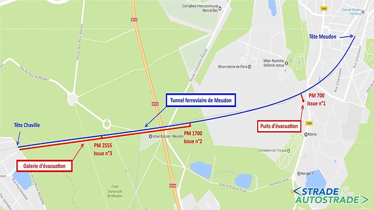
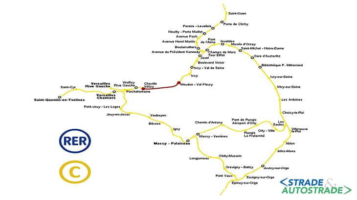
The RER-C suburban railway line of Paris connects the West and the South side of the city, for an overall length of 180 km. Between the stations of Meudon Val-Fleury and Chaville-Vélizy, in the Department Hauts-de-Seine (92), the line enters a tunnel of 3.350 m length, below the park of Chalais.
The tunnel, built in the framework of the public transport infrastructure works for the 1900 Paris Expo, is undergoing since 2017 an intervention for the securing of the emergency exits, considering an estimated traffic of 3 million passengers/years (SNCF data: https://ressources.data.sncf.com/).
The works consist of the construction of three new emergency exits, at chainages PM2555, PM1700 e PM700, and are overall divided in two lots.
The first lot, GC1, includes the realization of a new 1.680 m long tunnel, excavated by TBM (Tunnel Boring Machine) and connected to the existing tunnel at PM2500 and PM1700 through branches excavated with conventional methods.
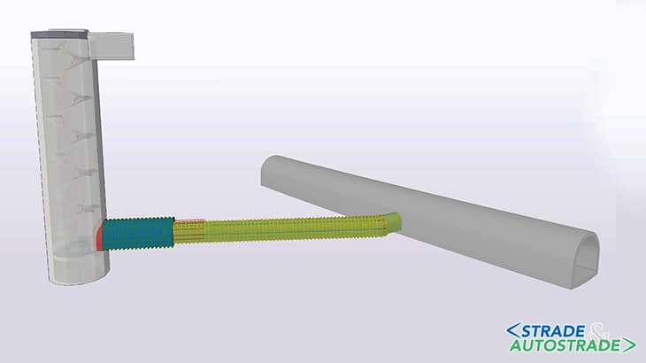
The second lot, GC2, is a localized emergency exit at PM700 disconnected from the new tunnel, consisting of a horizontal connection branch and a vertical diaphragm wall circular shaft.
The two lots GC1 and GC2 are built in parallel, under the supervision of the Maitrise d’Ouvrage SNCF (the Fraench National Railway Company) and the control of the Maître d’Oeuvre Ingerop (a French engineering consultant, with Project Management role).
Enser Srl, an Italian engineering firm with headquarters in Faenza (RA), has contributed to both lots with its French branch Enser France, with the role of:
- External reviewer for lot GC1, built by contractor Chantieres Modernes Construction of VINCI Group;
- Designer for the joint venture Parenge-Keller, up to design level EXE (Detailed and Constructive Design) including geotechnical supervision, for lot GC2.
Lot GC2
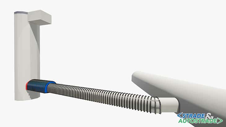
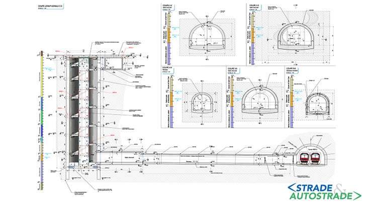
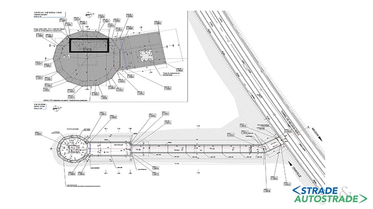
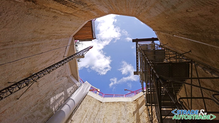
The realization of the emergency exit at chainage PM700 of the Meudon railway tunnel includes the construction of the circular shaft, with 9 m diameter, excavated within reinforced concrete diaphragm walls until a depth of 42.5 m from ground level, and a horzontal connection to the main tunnel with variable cross-section and a total length of 59.4 m.
The first stretch of the horizontal tunnel, excavated with conventional methods with a length of 45.9 m, has an equivalent diameter of 4.25 m and a soil cover of approx. 37 m.
This stretch, connected to the existing tunnel, gets larger near the well with an equivalent diameter of 6.14m over a length of 13.5 m, for a smoother flow of passengers to the stairs or to the lift in the circular shaft.
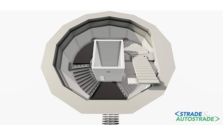
The internal structures of the shaft are simple and intended for a comfortable evacuation of the passengers. A helical stair surrounds the lift shaft, sustained by beams at the intermediate floors.
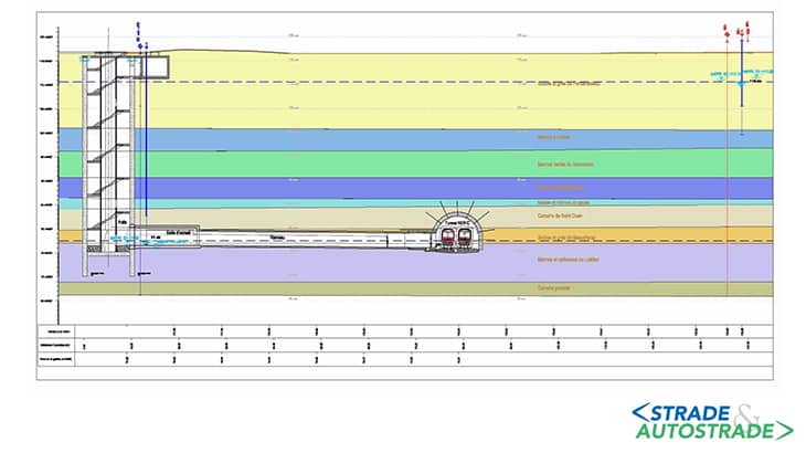
The geological context of lot GC2 is typical of the Paris area. In the 40m depth of subsoil, the following soil stratigraphy is encountered (from top to bottom):
- Remblais – heterogeneous deposits, sometimes with anthropogenic nature, of silty/clayey sands
- Fontainebleau Sands – fine sands vith varying clay content;
- À huitres Marls – Clayey marl with grey/green color;
- Green Clay – Green clay with strongly swelling behavior;
- Supragypseuses Marls – Clayey marls;
- Malm;
- Saint Ouen Limestone – Alternation of limestone marls and compact limestone, rather fractured;
- Beauchamp Sands – Fine sands, locally cemented;
- Marls and Caillasses – Limestone marls with sand lenses, small cemented blocks and limestone;
- Limestone bedrock.
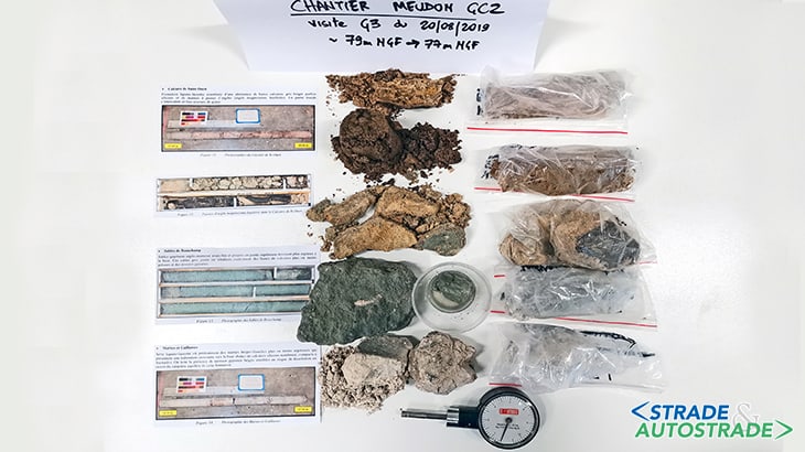
In the design of GC2 up to level EXE, Enser has carried out a geological and geotechnical supervision that was officially recognized as “Mission G3” according to the French norm NF-P-94-500 (2013).
This activity allowed the geotechnical engineers to verify, during construction, the correspondence between the design assumptions and the real soil stratigraphy: not only from a qualitative point of view, but also in terms of mechanical properties.
From a hydrogeological point of view, over the 40 m depth of the project extension, two perched groundwater tables can be identified within permeable soils, surrounded by layers with low permeability.
One can be found in the Fontainebleau Sands, supported by the reinforced concrete diaphragm walls of the shaft and not critical for the excavation.
The second groundwater table is found within the layer of Beauchamp Sands and the layer of Marls and Cailasses, at the same depth of the horizontal tunnel.
However, the low permeability of the Beauchamp Sands prevented the instability of the excavation front, allowing only for very limited water outflow.
The vertical shaft
The circular vertical shaft is constructed with reinforced concrete diaphragm walls having a thickness of 1m: the shape ensured the stability of the structure during excavation, making a propping system not necessary.
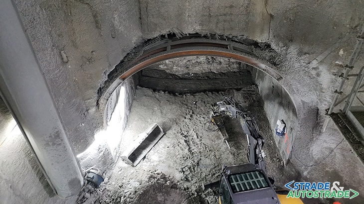
The initial cut for the horizontal tunnel is done after the in-situ casting of the reinforced concrete floor of the shaft. Local demolition of the diaphragm walls is made simpler by the utilisation, for the reinforcmenet of the surface to be demolished, of fiberglass elements.
The stability of the shaft during the above mentioned demolition is ensured not only by the “membrane” behaviour of the walls and floor as a whole, but also by the specific reinforcement designed at the sides of the opening, which receive an additional flexional load.
The structures inside the shaft are built after the excavation and the realisation of the horizontal tunnel. They mainly consist of the lift shaft, made by composition of prefabricated elements, and the helical stair supported by the diaphragm walls and by the lift shaft through horizontal cast-in-situ beams.
The shaft cover, which is the last element to be constructed, consist of structurally collaborating prédalles: this choice makes it possibile to avoid the use of formworks and provisional elements.
The emergency exit includes also a technical room, at the top but yet underground, connected to the main structures with a “waterstop” type expansion joint.
The horizontal connection tunnel
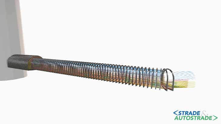
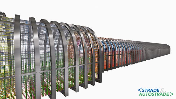
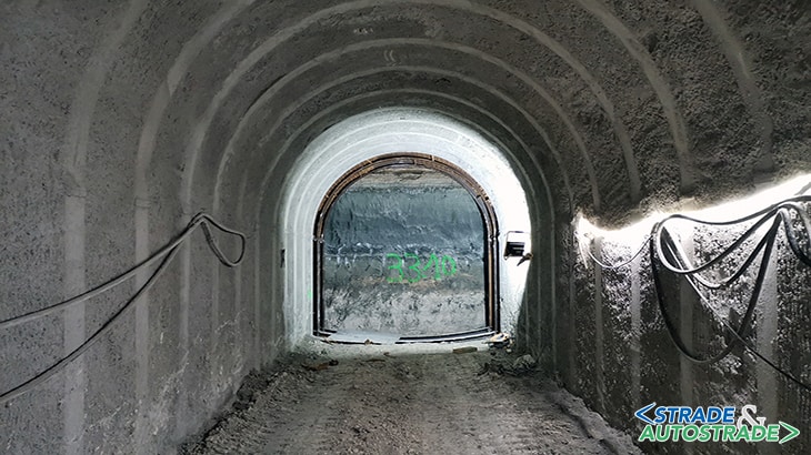
The tunnel that connects the vertical shaft to the main railway tunnel is excavated with conventional methods, with HEB200 beams as falsework for the initial part (with larger diameter) and HEB180 beams as falsework for the remaining length. Spacing of the beams is 80cm. The excavation cycle consists of the casting of a 18 cm thick concrete layer, sprayed over a welded mesh, after the placing of each beam.
For the 13.5 m initial stretch the placing of fiberglass bolts in the excavation front allowed safe operation with no expansion or collapse of the soil. Such bolts were not used beyond the initial excavation due to the good performance of the soil in terms of stability.
The modeling of the whole tunnel, calculated with the software Plaxis 3D (estimation of deconfinement rate) and Plaxis 2D (design of the tunnel temporary and final revetment), is carried out in a BIM environment with the software Tekla Structures: this allowed the integration of the design of the temporary reinforcements inside the geometry of the permanent ones.
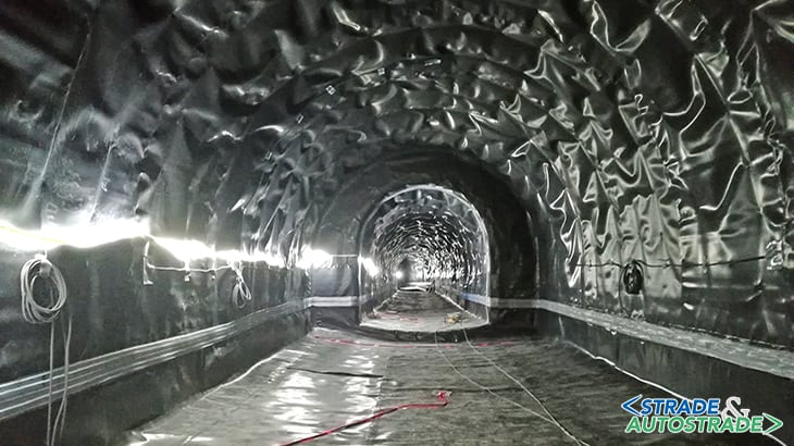
The permanent revetment of the tunnel is made of concrete, with a thickness of 400 mm for the first part of the tunnel and a thickness of 300 mm in the remaining length. It was cast after the installation of an impermeable membrane just below the temporary revetment.
Technical data
- Contracting Authority: SNCF Reseaux – Direction des Projets Franciliens
- General Contractor: Joint Venture between Parenge and Keller
- Preliminary Design: Ingerop Conseil et Ingénierie
- Detailed Design and Construction Design: Enser Srl through its branch Enser France
- Project Management: Ingerop Conseil et Ingénierie and SNCF Reseaux – Direction des Projets Franciliens
- Value of the Construction works: 6’100’000 Euro
- Duration of the Design works: approx. 500 days
- Delivery date: progressive deliveries
- End of Design works: May 2020
![]() Per la versione in Italiano: https://www.stradeeautostrade.it/gallerie-e-tunnelling/tunnel-di-meudon-luscita-di-soccorso-pm700/
Per la versione in Italiano: https://www.stradeeautostrade.it/gallerie-e-tunnelling/tunnel-di-meudon-luscita-di-soccorso-pm700/

